
 FIG·01
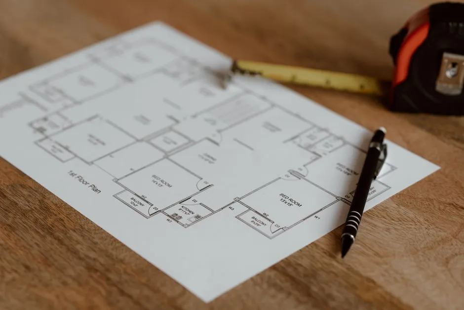
To import a PDF floor plan in ArchiMaster 3D, open a new or existing project, run the Import Floor Plan command, choose the PDF page, and place it as an underlay on the 2D plan. Then calibrate the underlay by entering a known dimension from the plan, such as a 24-foot wall or an 8,000 mm building length, so the drawing scale matches real life before you trace. The underlay is a visual reference only; ArchiMaster 3D does not convert PDF geometry into editable walls. The process works for PDF, JPG, PNG, and BMP files and gives you a fast, accurate way to turn a builder's PDF or a scanned blueprint into a fully editable home model. If you are new to the import pipeline, the features overview explains how underlays, layers, and 3D views stay synchronized.
- A PDF imports as a visual underlay in ArchiMaster 3D, not as editable walls, so tracing is always required.
- Calibrate using the longest clearly dimensioned line on the plan, ideally an exterior wall or overall building length, to minimize percentage scale error.
- Set your drawing units to feet, inches, or meters before import, because the scale tool uses the current project unit.
- Snap to orthogonal angles while tracing exterior walls, then overshoot at corners and use trim to create clean 90-degree joins.
- Hide or remove the underlay before exporting 2D elevations, 3D views, or construction drawings so the PDF does not appear in output.
Prepare the Source PDF Before Import
Start with the cleanest source file you can get. A vector PDF exported from CAD software imports with crisp lines and fewer artifacts than a photographed or badly scanned paper plan. If you only have paper, scan at 300 DPI in black and white or grayscale, save as PDF or PNG, and crop everything outside the drawing border. Rotate the image so the longest front wall runs as close to horizontal as possible; that prevents you from fighting an angled underlay while tracing. When the file has multiple pages, ArchiMaster 3D asks you to select one page, so print or export a single plan page before import. If lines disappear or look thick, flatten the PDF first in a PDF printer or viewer. A clean 300 DPI scan stays legible at 200 percent zoom, which matters when you are clicking corners.

Set the Project Units First
Open ArchiMaster 3D, create a new project or open an existing one, then set the project units before importing. If the PDF dimensions are in feet and inches, choose Imperial; if the plan is metric, choose meters or millimeters. Doing this first prevents the most common scale disaster: a 6,000 mm wall traced as 6,000 inches, which creates a house hundreds of feet long. The calibration step described later converts PDF units into real-world units using the current project setting, so changing units after tracing means rework, not a simple toggle. All four editions in the ArchiMaster 3D suite use the same unit and drawing engine, so the workflow is identical whether you are in Ultimate Home Design, Kitchen & Bath, or Expert. For edition features and one-time licensing, see pricing.
Import the Floor Plan as an Underlay
Use File > Import > Floor Plan or the Import button on the toolbar, then choose your PDF or image file. ArchiMaster 3D places the file as an underlay on the plan view; the underlay can be moved, rotated, and scaled, but its geometry is not converted into walls. If the imported plan looks tiny, that is expected. The software does not yet know how many real feet or meters one PDF unit represents. Drag the underlay near the drawing origin and keep it on a dedicated layer named PDF Underlay, so you can hide it later without hiding traced walls. Lock the underlay as soon as it is roughly in place; accidental drags during tracing are one of the biggest sources of misalignment. The underlay also becomes a visual double-check when you compare your modeled wall area against the printed floor area.
Calibrate Scale with a Known Dimension
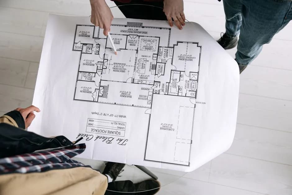
Select the scale or calibrate tool, then click the first point at one end of a clearly dimensioned line on the underlay and the second point at the other end. Type the true distance shown on the plan; ArchiMaster 3D resizes the underlay so that segment matches reality. Choose the longest clearly dimensioned line available, ideally an overall exterior wall or the full building length, because any small click error is spread over a larger distance and produces a smaller percentage scale error. After calibrating, verify by drawing a temporary wall or measurement line over a second dimension and checking the readout. If the second dimension is off, recalibrate from the longest line rather than nudging the underlay repeatedly.
- Select the scale or calibrate tool from the plan toolbar.
- Snap the first calibration point to one end of a dimensioned line.
- Snap the second point to the opposite end.
- Type the true distance in the current project units, such as 24 feet or 7,620 mm.
- Press Enter to apply, then test against a second dimension on the plan.
“Calibrate to the longest dimension on the plan, not the smallest, because a quarter-inch mistake on a 30-foot wall becomes a multiple-inch error on a 4-foot wall.”, ArchiMaster 3D scale workflow
Trace Walls and Openings Accurately
With the underlay scaled you can trace. Start with exterior walls and use the wall tool, snapping to corners while keeping the wall angle locked to horizontal or vertical. Do not try to stop exactly at each corner; draw the wall line past the corner, then use trim, extend, or join to clean the intersection. Overshooting and trimming gives you crisp 90-degree joins and avoids hairline gaps that later create 3D rendering artifacts. For door and window openings, place the framing wall first, then insert the opening or wall niche using the measured position from the plan. Because the home design software keeps plan, elevation, and 3D views synchronized, a correctly placed opening shows up in every view. Zoom to 200 percent at each opening and check lengths against the plan before moving on.
Common Scaling and Import Problems
Even with a clean PDF, two problems account for most scale errors: imported files with no visible page scale, and calibration points snapped to dimension arrows instead of the actual line endpoints. For the first, find the longest printed dimension on the plan, not the drawing scale bar, because some PDFs crop or distort the bar. For the second, zoom to the endpoint and snap to the line, not the text or arrowhead. If your walls are consistently short or long by the same percentage, your calibration line was too short or you changed project units after tracing. Recalibrate, then check one overall exterior dimension before redrawing.
- Imported PDF appears as a solid black box: convert to a newer PDF or re-scan at 300 DPI; some faxed or vector files include unsupported compression.
- Walls measure exactly 25.4 times too long or short: you traced with Imperial units while the plan was metric, or vice versa.
- Underlay moves while drawing: unlock, reposition, then lock the underlay layer before continuing.
- Second dimension does not match after calibrating: use a longer calibration line and zoom in on each endpoint.
- 3D view shows the PDF image in the sky: hide or delete the PDF Underlay layer before rendering or exporting.
- Can I import a PDF with multiple pages?
- Yes. ArchiMaster 3D asks you to choose one page during import. Export or print just the floor plan page first to keep the underlay clean and avoid selecting the wrong sheet.
- Do I have to trace every wall by hand?
- Yes. A PDF is a visual underlay, not an editable CAD file. Tracing is still required, but after calibration it typically takes less than an hour for an average single-family plan.
- What should I do if my imported plan is very small?
- Continue with calibration. The underlay has no scale until you enter a known distance. Select the scale tool and enter the longest clear dimension from the plan.
- Can I use the same workflow for an image of a floor plan?
- Yes. JPG, PNG, and BMP images work the same way as PDFs. Use a high-resolution, flat-facing photo or scan to keep lines crisp and endpoints easy to snap.
- Will the PDF show up in my final render or 2D export?
- Not if you hide the underlay layer. Keep the PDF on its own layer and turn that layer off before exporting 2D sheets or 3D views.
Ready to turn your PDF floor plan into an editable, render-ready model? Download the free trial of ArchiMaster 3D and work through the import and scaling workflow today.
Download Free TrialReady to design with confidence?
See which edition fits the space you’re designing.