
 FIG·01
You can model a load-bearing wall removal in ArchiMaster 3D before hiring a structural engineer by marking the bearing walls on a dedicated layer, saving a separate proposed plan, drawing the new beam or header at true scale, and exporting a dimensioned PDF of both the existing and proposed conditions. The model will not replace a stamped letter or beam calculation, but it gives the engineer a clean starting point and usually cuts one full round of site questions. ArchiMaster 3D is built for this residential workflow in ArchiMaster 3D home design software: walls, dimensions, and notes stay precise enough to read on paper. Start with an accurate as-built plan, and the structural conversation becomes a review instead of a discovery process.
- Mark load-bearing walls on their own locked layer before drawing any demolition, using joist direction, beam lines, and foundation clues.
- Duplicate the as-built file and work in a proposed version instead of deleting walls from the only copy; permit reviewers and engineers want both conditions.
- Dimension the clear opening from face of bearing point to face of bearing point, not from drywall to drywall.
- Place the new header at the real lumber, LVL, or steel depth, then export a scale-accurate PDF with room labels and notes.
- Send photos, a 3D view, and the PDF together; an engineer can confirm point loads faster from the model.
Start with an as-built plan before you change anything
A load-bearing wall removal depends on how accurately the existing conditions were drawn. Measure from fixed building edges, not from trim or baseboard. In ArchiMaster 3D, draw the full room set including ceiling height, visible joist direction, and any existing bulkheads, columns, or steel posts. Use the wall tool to draw current partitions at their actual thickness, typically 4-1/2 in. for a finished interior wall or 6-1/2 in. in older masonry construction. The more accurate this as-built base, the fewer surprise point loads the engineer finds later. If you are working from a scanner or old plans, verify a few key dimensions on site before trusting the model.

How to mark load-bearing walls in ArchiMaster 3D
ArchiMaster 3D will not auto-detect bearing conditions; you teach the model which walls carry load. Look for three clues: joists that end or overlap above the wall, a continuous beam or foundation below, and double top plates or metal strapping in exposed framing. In the software, create a new layer called Structure or Bearing and paint every load-bearing wall with a solid fill or heavier line weight. Keep that layer separate from the demolition layer, because the engineer reads bearing walls as the unchanged skeleton. For clarity, label each marked wall with a note such as 'assumed load-bearing, verify in field.' That phrase protects you when a non-load-bearing partition turns out to carry a point load from a roof valley above.
- Joists that end or overlap directly above the wall
- A continuous beam, foundation wall, or footing below the same line
- Double top plates, metal strapping, or a column in the basement
Create a demolition plan without destroying the as-built file
The fastest professional habit is to save the as-built plan, then choose Duplicate or Save As to create a proposed version. In the proposed file, show walls to be removed with a dashed outline or hatch, but leave the as-built envelope visible in light gray. ArchiMaster 3D keeps both views in one project sheet, so the engineer sees what goes away and what remains in the same export. Do not erase the wall from the as-built layer and call the file done. Building departments often ask for existing and proposed side by side. Keeping the original intact also means you can print a second drawing that proves ceiling joist direction was already captured before you opened the floor. This two-condition setup is where a purpose-built home design tool helps: the 2D plan stays dimension-accurate instead of becoming a loose sketch, as we covered in ArchiMaster 3D vs SketchUp: Faster 2D Floor Plans (2026).

Add the new beam or header and dimension the clear span
Switch to the structural library or draw the beam manually with the real member size. A 2x10, 2x12, LVL, or steel W-section should be modeled at actual depth and length, because a line does not tell the engineer whether the beam collar clears the ceiling. Dimension the clear span from the inside face of the support at each end, not from the drywall corners. Drywall and casing often hide the true bearing point by 1/2 in. to 2 in. on each side. If the beam sits under an existing ceiling joist, model it snug to the joist bottom so your 3D view catches height conflicts. Then label the proposed beam with both its assumed size and a note: 'size to be confirmed by engineer.' Across the ArchiMaster 3D editions, the drawing and PDF engine stays the same, so compare pricing to see which tier matches the structural library you need.
“Model the wall you are removing before you remove it; the as-built plan is the one drawing an engineer will trust.”, ArchiMaster 3D Journal
Export a dimensioned PDF and send it the right way
Use the PDF export in ArchiMaster 3D and set the scale to a standard paper size such as 1/4 in. = 1 ft or 1:50. Include the structural layer, the demolition or proposed layer, room names, door openings, and a small north arrow. Before exporting, switch dimension precision to inches and millimeters, and pull the dimension strings away from the plan so text does not sit on top of the beam. Export the as-built sheet and the proposed sheet as separate pages in one PDF. If your engineer works in SketchUp, you can also share the model using the process in How to Export ArchiMaster 3D to SketchUp Without Losing Textures or Scale, but the dimensioned PDF should remain the primary drawing because it is easy to mark up.
What to send your structural engineer besides the PDF
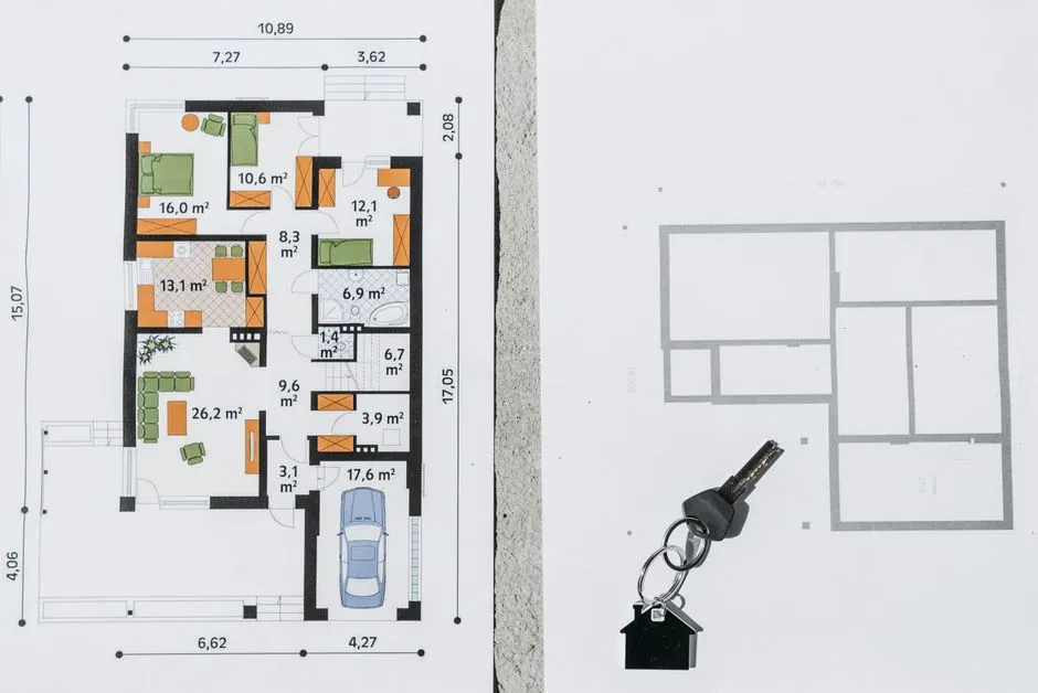
Send more than the drawing. Include site photos of the wall from both sides, a photo looking up at the joist direction in the ceiling if the cavity is open, and a 3D view from ArchiMaster 3D with the proposed beam highlighted. The 3D view helps an engineer spot point loads, duct conflicts, and bearing posts under the beam ends in seconds. Name the PDF clearly: '123 Main St existing and proposed wall removal 2026-08-17.pdf.' If the wall is already open, add a note with the actual joist size, spacing, and direction you measured. All ArchiMaster 3D products use the same true-to-scale libraries, so a clean model plus good photos gives the engineer a review package instead of a puzzle.
- Can ArchiMaster 3D automatically tell me if a wall is load-bearing?
- No. The software will not auto-detect structure. You identify load paths from joist direction, beams, and foundation, then mark the wall on a structure layer. The engineer or contractor confirms it in the field, and a stamped letter governs.
- What scale should I use when exporting a plan for a structural engineer?
- Use 1/4 in. = 1 ft or 1:50 on a standard sheet. Include both existing and proposed pages, dimension strings, room labels, and a note that the beam size is provisional. Export as PDF so dimensions stay legible.
- Do I need an architect before I send ArchiMaster 3D plans to a structural engineer?
- For most single wall removals, no. A clear as-built floor plan with joist direction and proposed opening is usually enough for the engineer to begin beam-sizing. Complex multi-wall changes may still need architectural drawings.
- Can I use ArchiMaster 3D plans for a building permit?
- They work well as supporting drawings and communication, but the permit office requires the engineer's sealed calculations and possibly a stamped drawing for structural work. Use the PDF to get the conversation started.
Mark your bearing walls and send a clean dimensioned PDF this week.
Download the free trialReady to design with confidence?
See which edition fits the space you’re designing.